REPAIR KIT MANUAL FOR SCHEUTEN PV MODULES
Introduction
This repair manual shows how to repair the junction boxes for Scheuten PV modules that house Solexus and Kostal junction boxes.
This repair is necessary due to the fire risk of the connection box. The repair must be performed by professional installers. Repairs by unqualified persons can create hazardous situations.
On-site repairs must be undertaken in compliance with existing safety regulations. In addition, repairs must be performed in suitable weather conditions, i.e. no rain and temperature above 5°C.
Click here to download the manual in PDF format (italian version)
Scope of delivery
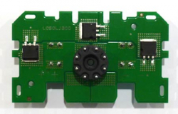
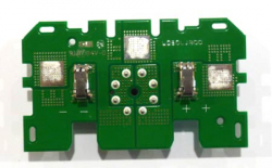
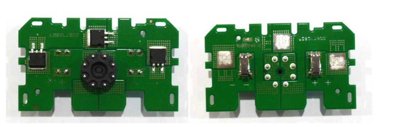
Scheuten uses two types of printed circuit board in the junction box, depending on the type of PV panel. The suggested replacement board can be used to replace both the Kostal and the Solexus board. The Replacement Kit consists of a circuit board fitted with metal connectors.
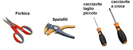
Equipment
Repair procedure
Switch off the PV installation and remove the PV panel from its frame.
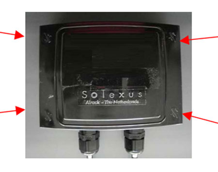
The cover of the junction box can be removed using a flat-head screwdriver to loosen the four clips at the corners (see image).
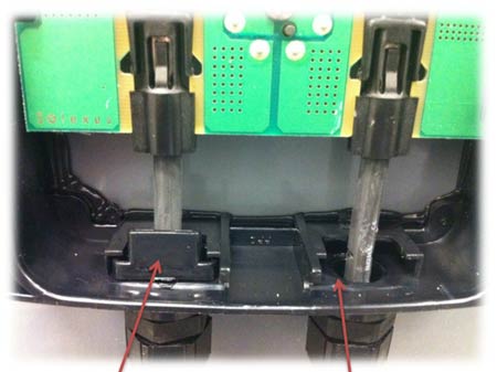
After removing the cover, remove the two wire blockers using the flat-head screwdriver.
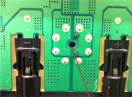
Remove the connector screws using a Phillips screwdriver, as shown in the image.
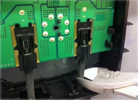
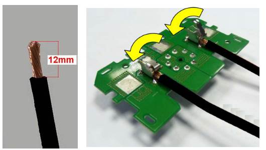
Cut the wires using wire cutters, as shown in the image.

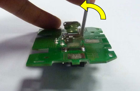
The circuit board can now be removed easily by pressing with a screwdriver on the four clips that secure the board. Remove the wires from the cable glands and strip them in preparation for re-wiring.
You can now insert the replacement circuit board. Open the cable clamps as shown in the image. Insert a small flat-head screwdriver in the upper slit of the clamp and twist it to release the clip. Be careful not to use too much force as you may deform the clip.
You can now insert the replacement circuit board. Open the cable clamps carefully, as shown in the image. Insert a small flat-head screwdriver in the upper slit of the clamp and twist it to release the clip. Be careful not to use too much force as you may deform the clip.
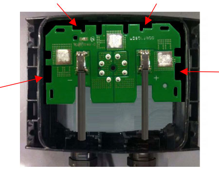
Now you can secure the wired circuit board in the connector block by pressing on the four fixing clips inside the block.
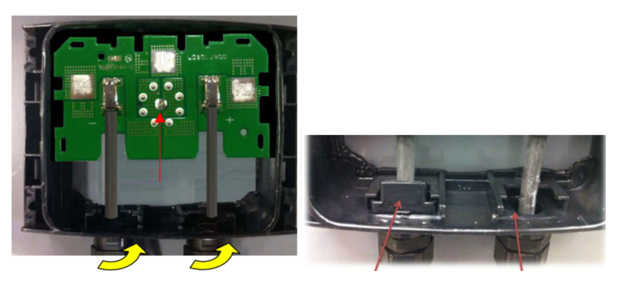
Secure the circuit board with the screws removed earlier, using a Phillips screwdriver. Tightly secure the two cable glands to prevent liquids and dust from entering the box. Replace the wire securing clips by pressing the "U" clips firmly in place.

Close the connection box with the cover, pressing on all four corners to ensure that the clips click in place securely, isolating the box from water or dust infiltrations.